E-Mail:gaobo@bondaequip.com
Tel:+86-535-6801125


This project is located in Guinea, with a designed wastewater treatment capacity of 50 cubic meters per day. The wastewater is domestic sewage with the following characteristics: ambient temperature, CODcr ≤ 400 mg/L, BOD₅ ≤ 200 mg/L, SS ≤ 300 mg/L, and pH 6–9. According to the client's requirements, the treated effluent shall meet the urban miscellaneous water quality standards (GB/T 18920-2020) for reuse in landscaping and road watering.
The target effluent quality is as follows: BOD₅ ≤ 10 mg/L, turbidity ≤ 10 NTU, ammonia nitrogen ≤ 8 mg/L, pH 6–9, color ≤ 30, anionic surfactants ≤ 0.5 mg/L, and total coliforms ≤ 3 MPN/L.
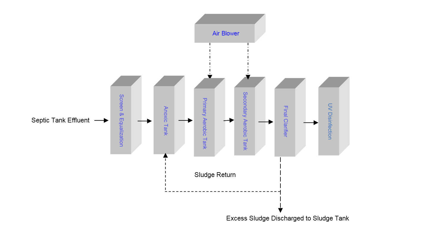
Given the specific characteristics of the wastewater from this camp, the proposed treatment process employs a conventional "A/O/O biological contact oxidation + disinfection" system. This process is relatively simple, easy to operate, cost-effective, and provides stable effluent quality. The primary equipment is fabricated from steel. The treated effluent can be reclaimed as reclaimed water for non-potable uses such as irrigation and toilet flushing.
2.1 Design Objectives
This design proposal is prepared to achieve the following objectives:
1. Analyze the characteristics of the wastewater;
2. Define the project scope and design parameters;
3. Propose a feasible construction plan through technical and economic comparison;
4. Develop the engineering design scheme;
5. Provide a basis for project investment estimation and cost analysis.
2.2 Design Basis
This report is prepared based on the following documents:
1. Urban Miscellaneous Water Quality Standard (GB/T 18920-2020);
2. Basic data on wastewater quality and quantity provided by the client;
3. The equipment shall be installed in an underground (buried) configuration based on actual site conditions.
2.3 Design Codes and Standards
The design, construction, and installation of this project shall comply with the following national technical codes and standards:
1. Code for Design of Outdoor Wastewater Engineering (GB 50014-2006, 2014 Edition);
2. Structural Design Code for Water Supply and Drainage Engineering Structures (GB 50069-2002);
3. Structural Design Code for Pipelines of Water Supply and Drainage Engineering (GB 50332-2002);
4. Code for Construction and Acceptance of Water Supply and Drainage Pipeline Engineering (GB 50268-2008);
5. Code for Construction and Acceptance of Water Supply and Drainage Structures (GB 50141-2008);
6. Code for Design of Power Supply and Distribution Systems for Industrial and Civil Buildings (GB 50052-2009);
7. Code for Design of Low-Voltage Electrical Installations (GB 50054-2011);
8. Code for Design of Cables of Electric Power Engineering (GB 50217-2007);
9. Operating Procedures for Anti-Corrosion Engineering Construction (GB 50212-2002);
10. Specification for Welding and Acceptance of Reinforcing Steel Bars (JGJ 18-2012).
2.4 Design Principles
2.4.1 Fundamental Principles
1. The design shall be carried out in accordance with the principles of advanced technology, practicality, reliability, and cost-effectiveness. The selected treatment process shall be advanced, practical, mature, and reliable, capable of handling significant fluctuations in both water quality and flow rate, ensuring compliant effluent discharge.
2. The process layout shall be rationally arranged to optimize the overall system efficiency. The treatment process shall be carefully optimized to minimize construction costs while ensuring safe, economical, and stable system operation, achieving optimal treatment performance with minimal investment.
3. The selected treatment process shall offer reasonable operating costs, balancing treatment efficiency with reduced equipment investment.
4. Advanced and reliable equipment and automatic control systems shall be adopted to maximize automation and optimization control during wastewater treatment, reducing maintenance and management workload. The design shall provide targeted engineering layouts for both facilities and equipment, ensuring convenient and reliable operation.
5. Low-noise, energy-efficient power equipment shall be prioritized, with vibration damping and noise reduction measures implemented to prevent noise pollution.
6. The overall environmental impact of the wastewater treatment facility shall be harmonized with the surrounding environment. The layout shall be rationally arranged to minimize the project footprint while optimizing the treatment process design.
2.4.2 Design Approach
This project adopts a combined treatment process of "anoxic + aerobic + aerobic + sedimentation + disinfection." Wastewater first passes through a septic tank for primary sedimentation to remove larger impurities and floating matter such as paper and fecal solids. The effluent then enters the biological treatment system for further treatment, significantly enhancing biological treatment efficiency. After biological treatment and sedimentation to separate suspended sludge, the wastewater undergoes disinfection before being discharged in full compliance with the required standards.
2.5 Scope of Work and Scope of Supply
Scope of Work:
Project scheme design
Equipment fabrication
Supervisory installation guidance
System commissioning
Scope of Supply:
From the inlet boundary of the equalization tank to the outlet header pipe of the treatment system.
3.1 Wastewater Flow Rate
The wastewater to be treated in this project is domestic sewage with a flow rate of 50 m³/day. The main pollutants are BOD₅, CODcr, SS, and ammonia nitrogen.
3.2 Design Influent and Effluent Quality
Design Influent Quality:
Domestic sewage at ambient temperature
CODcr ≤ 400 mg/L
BOD₅ ≤ 200 mg/L
SS ≤ 300 mg/L
pH 6–9
Treated Effluent Quality Standards:
BOD₅ ≤ 10 mg/L
Turbidity ≤ 10 NTU
Ammonia nitrogen ≤ 8 mg/L
pH 6–9
Color ≤ 30
Anionic surfactants ≤ 0.5 mg/L
Total coliforms ≤ 3 MPN/L
3.3 Process Scheme

Tel: +86-535-6801125
Tel: +86-13853509591

Email: gaobo@bondaequip.com